- 您现在的位置:买卖IC网 > Sheet目录986 > KIT3376MMA7368L (Freescale Semiconductor)KIT EVAL 3AXIS ANLG ACCELEROMETR
�� �
�
�BASIC� CONNECTIONS�
�Pin� Descriptions�
�Top� View�
�N/C�
�PCB� Layout�
�POWER� SUPPLY�
�N/C�
�X� OUT�
�Y� OUT�
�Self� Test�
�N/C�
�N/C�
�V� DD�
�V� SS�
�Sleep�
�C�
�C�
�V� RH�
�P0�
�V� DD�
�V� SS�
�C�
�Z� OUT�
�N/C�
�V� SS�
�V� DD�
�N/C�
�N/C�
�Self� Test�
�P1�
�Sleep�
�Figure� 4.� Pinout� Description�
�Table� 3.� Pin� Descriptions�
�Pin� No.�
�Pin� Name�
�Description�
�X� OUT�
�Y� OUT�
�Z� OUT�
�C�
�C�
�C�
�A/D� IN�
�A/D� IN�
�A/D� IN�
�1�
�2�
�3�
�4�
�5�
�6�
�7�
�8�
�9�
�10�
�11�
�12�
�13�
�14�
�N/C�
�X� OUT�
�Y� OUT�
�Z� OUT�
�V� SS�
�V� DD�
�Sleep�
�NC�
�NC�
�NC�
�N/C�
�N/C�
�Self� Test�
�N/C�
�No� internal� connection�
�Leave� unconnected�
�X� direction� output� voltage�
�Y� direction� output� voltage�
�Z� direction� output� voltage�
�Power� Supply� Ground�
�Power� Supply� Input�
�Logic� input� pin� to� enable� product� or� Sleep� Mode�
�No� internal� connection�
�Leave� unconnected�
�Leave� unconnected�
�Leave� unconnected�
�Unused� for� factory� trim�
�Leave� unconnected�
�Unused� for� factory� trim�
�Leave� unconnected�
�Input� pin� to� initiate� Self� Test�
�Unused� for� factory� trim�
�Leave� unconnected�
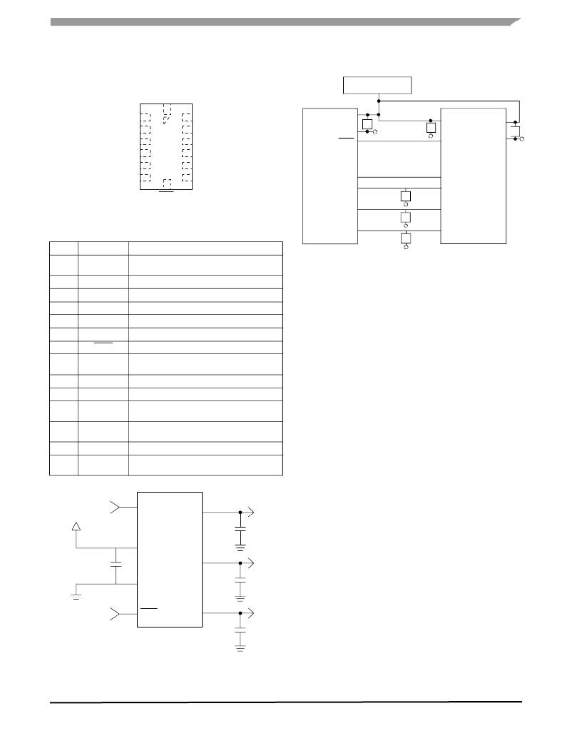
�Figure� 6.� Recommended� PCB� Layout� for� Interfacing�
�Accelerometer� to� Microcontroller�
�NOTES:�
�1.� Use� 0.1� μF� capacitor� on� V� DD� to� decouple� the� power�
�source.�
�2.� Physical� coupling� distance� of� the� accelerometer� to�
�the� microcontroller� should� be� minimal.�
�3.� Place� a� ground� plane� beneath� the� accelerometer� to�
�reduce� noise,� the� ground� plane� should� be� attached� to�
�all� of� the� open� ended� terminals� shown� in� Figure� 6� .�
�4.� Use� a� 0.1uF� capacitor� on� the� outputs� of� the�
�accelerometer� to� minimize� clock� noise� (from� the�
�switched� capacitor� filter� circuit).�
�5.� PCB� layout� of� power� and� ground� should� not� couple�
�power� supply� noise.�
�6.� Accelerometer� and� microcontroller� should� not� be� a�
�high� current� path.�
�7.� A/D� sampling� rate� and� any� external� power� supply�
�switching� frequency� should� be� selected� such� that�
�XOUT�
�VDD�
�Logic�
�Input�
�13�
�Self� Test�
�MMA7368L�
�2�
�0.1� μ� F�
�they� do� not� interfere� with� the� internal� accelerometer�
�sampling� frequency� (11� kHz� for� the� sampling�
�frequency).� This� will� prevent� aliasing� errors.�
�6�
�VDD�
�0.1� μF�
�5�
�VSS�
�YOUT�
�3�
�0.1� μ� F�
�Logic�
�Input�
�7�
�Sleep�
�ZOUT�
�4�
�0.1� μ� F�
�Figure� 5.� Accelerometer� with� Recommended�
�Connection� Diagram�
�MMA7368L�
�Sensors�
�Freescale� Semiconductor�
�5�
�发布紧急采购,3分钟左右您将得到回复。
相关PDF资料
KIT34844AEPEVBE
KIT EVAL BOARD 10CH LED BACKLGHT
KIT3803MMA7660FC
KIT EVALUATION FOR MMA7660FC
KITMMA9550LEVM
KIT EVALUATION FOR MMA955XL
KITMMA955XLEVM
KIT EVALUATION FOR MMA955XL
KITMPL115A1EVB
KIT EVALUATION FOR MPL115A1
KITMPL115A1SPI
KIT EVALUATION FOR PL115A1SP1
KITMPL115A2I2C
KIT EVALUATION FOR PL115A2I2C
KITMPVZ5004EVK
KIT EVAL PRESSURE SENS BOARD
相关代理商/技术参数
KIT3376MMA7368LC
功能描述:加速传感器开发工具 3AXIS Angl Accelero Eval Kit RoHS:否 制造商:Murata 工具用于评估:SCA3100-D04 加速:2 g 传感轴:Triple Axis 接口类型:SPI 工作电压:3.3 V
KIT33794DWBEVM
功能描述:位置传感器开发工具 33794DWB ODS-NITRON EVAL
RoHS:否 制造商:Microchip Technology 工具用于评估: 接口类型: 工作电压:
KIT33794EKEVM
功能描述:KIT EVALUATION HARDWARE 33794 RoHS:否 类别:编程器,开发系统 >> 过时/停产零件编号 系列:* 标准包装:1 系列:- 传感器类型:CMOS 成像,彩色(RGB) 传感范围:WVGA 接口:I²C 灵敏度:60 fps 电源电压:5.7 V ~ 6.3 V 嵌入式:否 已供物品:成像器板 已用 IC / 零件:KAC-00401 相关产品:4H2099-ND - SENSOR IMAGE WVGA COLOR 48-PQFP4H2094-ND - SENSOR IMAGE WVGA MONO 48-PQFP
KIT33800EKEVME
功能描述:电源管理IC开发工具 ENGINE CONTROL INTEGRATE RoHS:否 制造商:Maxim Integrated 产品:Evaluation Kits 类型:Battery Management 工具用于评估:MAX17710GB 输入电压: 输出电压:1.8 V
KIT33810EKEVME
功能描述:电源管理IC开发工具 AUTOMOTIVE ENGINE CONTROL RoHS:否 制造商:Maxim Integrated 产品:Evaluation Kits 类型:Battery Management 工具用于评估:MAX17710GB 输入电压: 输出电压:1.8 V
KIT33811EGEVBE
功能描述:电源管理IC开发工具 SOLENOID MONITOR INTEGRA RoHS:否 制造商:Maxim Integrated 产品:Evaluation Kits 类型:Battery Management 工具用于评估:MAX17710GB 输入电压: 输出电压:1.8 V
KIT33812ECUEVME
功能描述:电源管理IC开发工具 SINGLE CYL S12 ENG CONTR RoHS:否 制造商:Maxim Integrated 产品:Evaluation Kits 类型:Battery Management 工具用于评估:MAX17710GB 输入电压: 输出电压:1.8 V
KIT33812ECUEVME
制造商:Freescale Semiconductor 功能描述:Small Engine Control Reference Design